Tools needed:
1.
PC running Windows Operating
System (OS)
2.
ArduinoIDE (installed)
3.
Arduino Kit
4.
LCD Module
5.
Potentiometer (5KΩ or 10KΩ)
6.
Resistor of 220Ω
7.
Breadboard
8.
Jumper
wires
Turn on the PC, connect and configure the Arduino
provided to you. Run test examples provided within Arduino IDE to verify if it
is properly connected or not.
Note:
The information and concepts discussed in this lab
manual are in sufficient detail but are still not exhaustive. It is assumed
that all these concepts are already taught to you in your ITC theory class.
1. Interface LCD
Module with Arduino
Liquid
Crystal Display (LCD)
A Liquid Crystal Display commonly
abbreviated as LCD is
basically a display unit built using Liquid
Crystal technology. When we build
real life/real world electronics based projects, we need a medium/device to
display output values and messages. The most basic form of electronic display
available is 7 Segment display – which has
its own limitations. The next best available option is Liquid Crystal Displayswhich comes in different size specifications. Out of all available LCD
modules in market, the most commonly used one is 16x2 LCD Module which
can display 32 ASCII characters in 2 rows (16 characters in 1 row).
16x2 LCD Module Pin Out Diagram
The LCD module has 16 pins and can be operated in 4-bit mode or
8-bit mode. Here we are using the LCD module in 4-bit mode. Before going in to
the details of the project, let’s have a look at the JHD162A LCD module. The pin
layout of a JHD162A LCD pin diagram is given below:
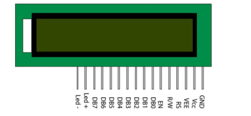
The name and function of each pin of the 16×2 LCD module is given
below.
|
Pin#
|
Name
|
Purpose
|
|
1
|
GND or VSS
|
Ground pin of
the LCD module.
|
|
2
|
VCC
or VDD
|
Power to LCD
module (+5V supply is given to this pin)
|
|
3
|
VEE
or Vo
|
Contrast adjustment pin. This is done
by connecting the ends of a 10K potentiometer to +5V and ground and then
connecting the slider pin to the VEE pin. The voltage at the VEE pin defines
the contrast. The normal setting is between 0.4 and 0.9V.
|
|
4
|
RS
|
Register select
pin.The JHD162A has two registers namely command register and data register. Logic
HIGH at RS pin selects data register and logic LOW at RS pin selects command
register. If we make the RS pin HIGH and feed an input to the data lines (DB0
to DB7), this input will be treated as data to display on LCD screen. If we
make the RS pin LOW and feed an input to the data lines, then this will be
treated as a command ( a command to be written to LCD controller – like
positioning cursor or clear screen or scroll).
|
|
5
|
R/W
|
Read/Write
modes. This pin is used for selecting between read and write modes. Logic
HIGH at this pin activates read mode and logic LOW at this pin activates
write mode.
|
|
6
|
E or EN
|
This pin is
meant for enabling the LCD module. A HIGH to LOW signal at this pin will
enable the module.
|
|
7-14
|
DB0 to DB7
|
These are data
pins. The commands and data are fed to the LCD module though these pins.
|
|
15
|
Led+
|
Anode of the
back light LED. When operated on 5V, a 560 ohm resistor should be connected
in series to this pin. In Arduino based projects the back light LED can be
powered from the 3.3V source on the Arduino board.
|
|
16
|
Led-
|
Cathode of the back light LED.
|
Interfacing
LCD Module with Arduino
Interface the LCD Module with Arduino based on the
following schematic and layout diagrams using jumper wires, a resistor and a
potentiometer.

Schematic diagram of LCD
module connected with Arduino UNO

Layout diagram of LCD module
connected with Arduino UNO.
Connectionsto
be made are listed in a table below:
|
S#
|
LCD Pin Name
|
Arduino Pin
|
|
1
|
Vss
|
GND
|
|
2
|
Vdd
|
5V
|
|
3
|
Vo
|
Middle leg of potentiometer
|
|
4
|
Rs
|
12
|
|
5
|
R/W
|
GND
|
|
6
|
E or EN
|
11
|
|
7
|
D4
|
5
|
|
8
|
D5
|
4
|
|
9
|
D6
|
3
|
|
10
|
D7
|
2
|
|
11
|
LED+
|
5V through 220Ω resistor.
|
|
12
|
LED-
|
GND
|
2. Display text
string on LCD:
Conventionally, the first code to test an output
device that can show text is to display the string "Hello World!" on
to it.
Sample code 1: "Hello, World!"
#include <LiquidCrystal.h>
// initthe library by associating any needed LCD interface pin
// with the arduino pin number it is connected to
const int rs = 12, en = 11, d4 = 5, d5 = 4, d6 = 3, d7 = 2;
LiquidCrystal lcd(rs, en, d4, d5, d6, d7);
void setup()
{
// set up the LCD's number of
columns and rows:
lcd.begin(16, 2);
// Print a message to the LCD.
lcd.print("Hello, World!");
}
void loop()
{
}
Sample code 2: Blinking "Hello, World!"
#include <LiquidCrystal.h>
// init the library by associating any needed LCD interface pin
// with the arduino pin number it is connected to
const int rs = 12, en = 11, d4 = 5, d5 = 4, d6 = 3, d7 = 2;
LiquidCrystal lcd(rs, en, d4, d5, d6, d7);
void setup()
{
// set up the LCD's number of
columns and rows:
lcd.begin(16, 2);
// Print a message to the LCD.
lcd.print("Hello,
World!");
}
void loop()
{
// Turn off the display:
lcd.noDisplay();
delay(500);
// Turn on the display:
lcd.display();
delay(1000);
}
3. Reading analog
inputs:
It's relatively simple to use an Arduino to measure voltages. The
Arduino has several analog input pins that connect to an analog-to-digital
converter (ADC) inside the Arduino. The Arduino ADC is a 10-bit converter,
meaning that the output value will range from 0 to 1023. We will obtain this
value by using the analogRead()
function. If you know the reference voltage-- in this case we will use 5V--you
can easily calculate the voltage present at the analog input (this is known as
calibration).
In this experiment, we
will make digital voltmeter capable of measuring up to 5V using an Arduino
board and a 16x2 LCD.
Use a jumper wire connected
to Arduino pin A0 to connect to the point whose voltage is to be measured with
respect to the GND.
Digital Voltmeter Sample Code:
Following is the code
for the DVM.
#include "LiquidCrystal.h"
const int rs = 12, en = 11, d4 = 5,
d5 = 4, d6 = 3, d7 = 2;
LiquidCrystal lcd(rs, en, d4, d5,
d6, d7);
float input_voltage = 0.0;
float temp=0.0;
void setup()
{
Serial.begin(9600); //opens
serial port, sets data rate to 9600 bps
lcd.begin(16, 2); //set up
the LCD's number of columns and rows:
lcd.print("DVM by i170999");
}
void loop()
{
//Conversion formula for voltage
int analog_value = analogRead(A0);
input_voltage = (analog_value * 5.0) / 1024.0;
if (input_voltage < 0.1)
{
input_voltage = 0.0;
}
Serial.print("v = ");
Serial.println(input_voltage);
lcd.setCursor(0, 1);
lcd.print("Voltage = ");
lcd.print(input_voltage);
delay(300);
}
Note:
The lines of code that begin with
'Serial.' aren't needed for interfacing with LCD. Instead they are to print out
the output on the Serial Monitor. It is a good tool for debugging to see
whether the code is working fine or not. If the LCD is not showing anything but
the Serial Monitor is, may mean the connections with the LCD module are faulty.
No comments:
Post a Comment